MEG4 is the new safety guideline that aims to develop a more robust framework for mooring line design, selection, operation and ultimately safe rope retirement. Amongst others, it defines the whole process for purchasing and testing mooring lines and tails.
Although standards, guidelines and recommendations have already been available for mooring systems, incidents that harmed ship and terminal personnel have occurred nevertheless during mooring. Many seafarers and terminal operators became victims of mooring lines recoiling due to failure under tension. A more human-centered design, equipment selection, inspection and maintenance of mooring lines was necessary to ensure safer operations. Thus, the fourth edition of the Mooring Equipment Guidelines (MEG4) came to establish the best known mooring technology and practice till today.
“Our investigation revealed widespread misunderstanding over the properties, use and maintenance of specific types of line.”
Steve Clinch MNM, Chief Inspector of Marine Accidents
With his statement, Steve Clinch made clear how important it was for a widely adopted new terminology in maritime to be established. Moreover, MEG4 provides directions regarding mooring line retirement timeframes before they fail, so that the number of accidents to seafarers and terminal staff during mooring and unmooring operations would be reduced.
These guidelines provide mooring rope manufacturers and users with the following:
The role of equipment manufacturers in safe operations is decisive. For manufacturers, following the MEG4 means crafting loose equipment with enhanced safety taking into consideration material behavior, performance testing, risk assessment and safety margins of mooring lines and mooring tails.
But how should all forces applied on the ship be measured? What factors dictate how the applied forces are distributed to the ship’s mooring lines? In this article we will be answering those questions and we will discuss the new terminology of MEG4, and the requirements a ship’s rope equipment should follow.
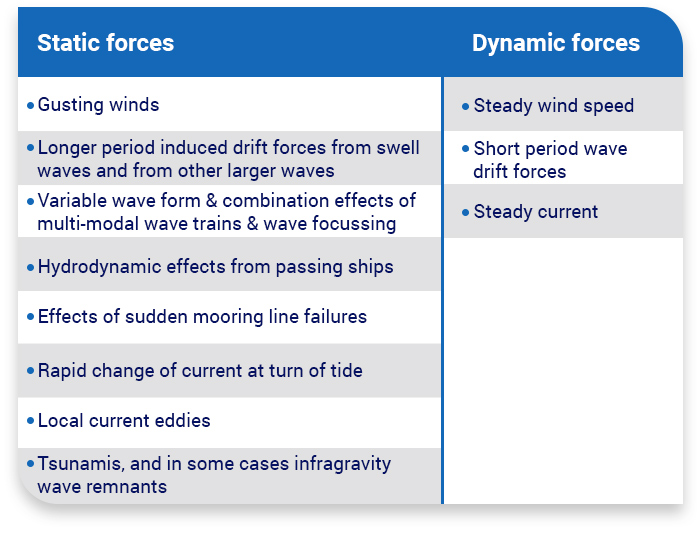
Every time a ship has been berthed, she must resist some constant or dynamic forces deriving from the following factors:
The ship moves directly and immediately with the impact from each wave, but she also endures the action of steady or changing drift forces created by wave reflections off the hull and other structures around the vessel.
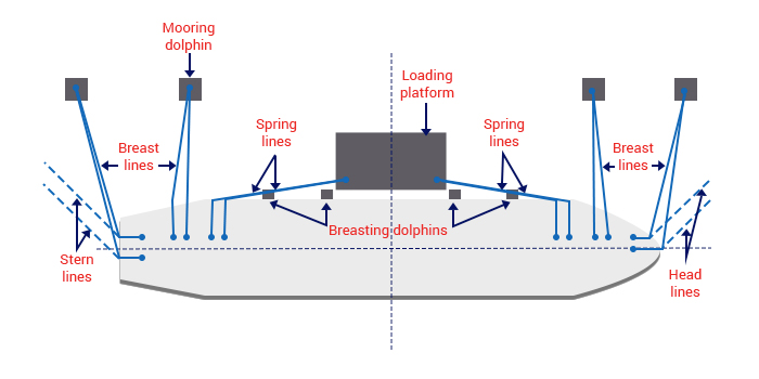
Every vessel needs a mooring system to withstand these forces, and ensure crews are not exposed to avoidable risks during mooring operations, and while a ship is berthed. For general applications, the mooring pattern used must be able to cope with environmental forces from any direction sharing the load equally. Load distribution is critical and that’s why the use of mixed moorings for similar service should be avoided.
If a new mooring pattern is applied, risk should be assessed again due to the fact that
lines need to always operate within safety margins throughout their service life.
However, high winds and sea currents from certain directions might make an asymmetrical mooring arrangement a more effective and wise option. Exposed terminals can be subject to more extreme environmental forces. Visiting ships may need to enhance the mooring equipment or supplement the mooring restraints with appropriate shore based equipment which may include additional mooring lines run from shore to the ship’s bitts.
In any case, safe mooring means taking into account:
Computer programs are widely available to calculate mooring forces for any combination of wind and current speeds and angles
Software simulations are the most effective way to test the mooring system of an existing or planned ship at a terminal known to have unusual environmental conditions or mooring layout.
Ship design MBL: The MBL of new, dry mooring lines for which a ship’s mooring system is designed, that meets standard environmental criteria restraint requirements. System design will establish the effective ship design MBL for each mooring line in the standard mooring pattern. MBL is the fundamental factor used to ensure that all other parts of the mooring system are correctly specified.
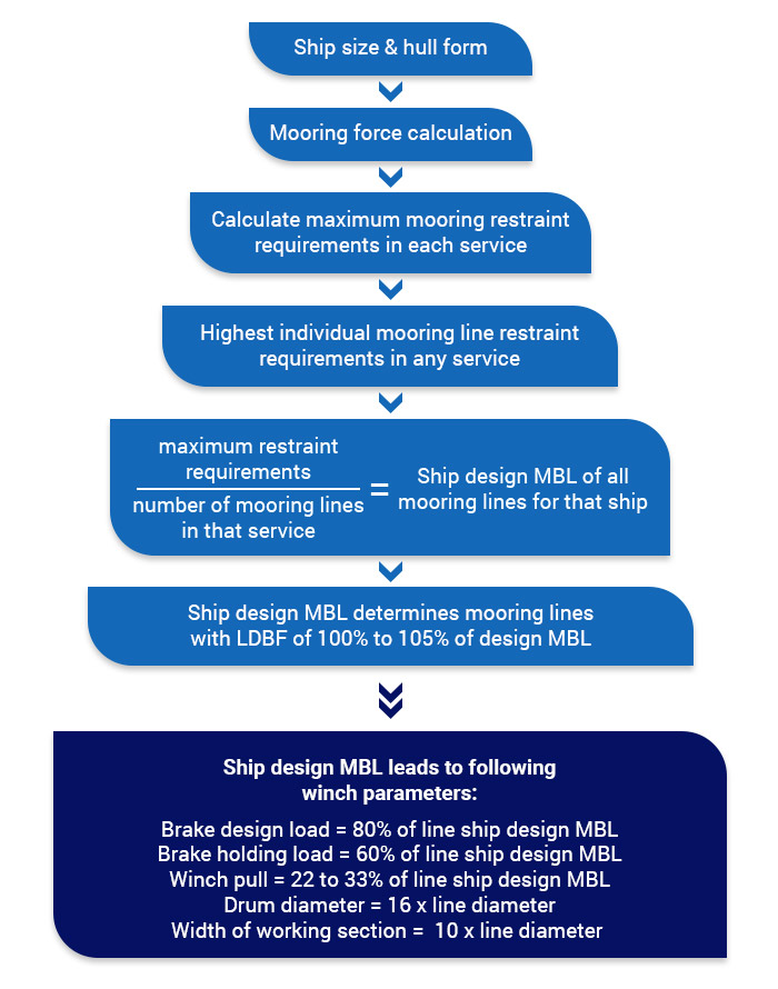

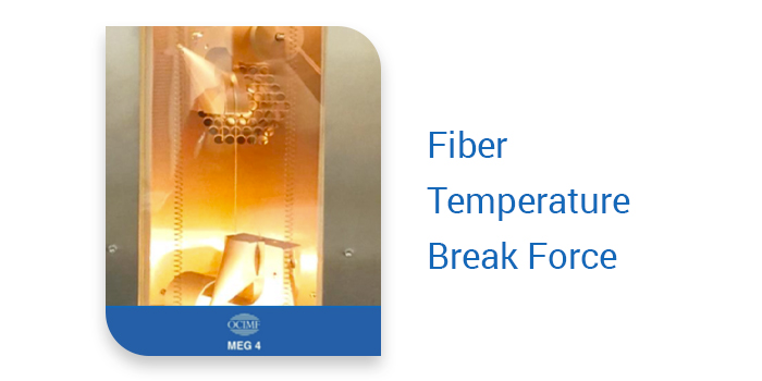
Line Design Break Force (LDBF): The minimum force at which a new, dry, spliced mooring line will break when tested. This is for all mooring line and tail materials except those manufactured from nylon. They need to be tested wet and spliced.= because nylon lines change strength characteristics once exposed to water, and generally do not fully dry to their original state.
Working Load Limit (WLL): The maximum load that a mooring line should be subjected to in operational service, calculated using standard environmental criteria.
Line Management Plan (LMP): It is used to manage the operation and retirement of mooring lines and tails. The LMP also documents the requirements, assumptions and evaluation methods used in determining the line retirement criteria.
Managing a ship’s lines includes:
Mooring System Management Plan (MSMP): It is part of the requirements to ensure risks are managed through the safe design and operation of mooring systems. A complete Mooring System & Management Plan has to acknowledge the following:
Mooring equipment and arrangements deal with the number, location and size of deck winches, mooring lines, bollards and fairleads to provide an effective, balanced mooring pattern. The term mooring pattern refers to the geometric arrangement of mooring lines between the ship and the berth. On the other hand Mooring equipment strength involves material properties, maintenance schemes, installation plan and storage.
Different environmental load directions and mooring point locations can be encountered at various terminals. Stiffness plays an important role in the mooring system, since it is a measure of its ability to stretch under load. A low stiffness line will stretch more than a high stiffness line. Low stiffness lines absorb higher dynamic loads, and they are prefered for STS transfer operations or at terminals susceptible to waves, swell or passing ship forces.
But extremely low stiffness – such as all nylon lines – can also mean that the ship will move further in her berth. This could cause problems with marine loading arms or hoses and operating envelopes. Moreover, stored energy in a low stiffness line will snap-back (recoil effect) unpredictably if released on sudden failure, and can cause injury to personnel plus damage to the ship’s equipment.
Something else worth mentioning about MEG4 mooring requirements is the comparison between wire and high modulus ropes. Wire mooring lines are very stiff. Typical elongation of a wire line under load is about 1% of wire length. Under an equivalent load, a polypropylene rope may stretch ten times as much as a wire. Therefore, if a wire is run out parallel to a conventional fiber line, the wire will carry almost the entire load while the fiber line carries practically none.
Snap-back (also known as recoil) is the tendency of the broken ends of a tensioned line to draw back rapidly after a line breaks. As a line comes under tension, it is stretched and stores energy. Snap-back is the result of the sudden release of that energy. Although snap-back is possible in all types of line, some synthetic lines have more inherent elasticity (are less stiff) than others, and so the danger of recoiling can be more severe.
Even long wire lines, or HMSF lines with lower stretch capability, can stretch enough to snap-back and release considerable amounts of energy. This stretch capability, and therefore the amount of stored energy, can be further increased if a synthetic tail is connected to the mooring line.
Snap-back presents a significant risk to the safety of any personnel working in mooring areas on a ship, tug or quay. Measures should be put in place to mitigate the risk. For new ships, it is recommended that designers and ship operators work together to remove personnel exposure to snap-back during mooring operations. This can be done by taking a human-centered approach to the design.
Permanently marking snap-back danger zones on the deck is not recommended. Although there are areas of increased snap-back risk, it is not possible to accurately calculate the whole range of snap-back danger zones to ensure personnel safety. Marking snap-back danger zones creates a false sense of safety for personnel standing outside of a marked danger zone.
The stiffness values can be obtained from mooring line manufacturers or suppliers.
The stiffness of the ship’s lines should not undermine staff safety in any of these mooring cases. High modulus ropes are gaining ground now because of their low elasticity/high stiffness properties and their reduced snap-back phenomenon.
The different stiffness of multiple line materials may affect how forces are distributed into the mooring system. When cow hitch knots are used in mooring, high and low stiffness ropes are combined.
The stiffness of a mooring line primarily depends on the following factors:
Choosing Katradis high performance ropes for your operations means you buy from a manufacturer that follows a strict quality policy. Our continuous R&D and testing activities along with many years of experience provide safety to your staff and ensure specification standards of manufacturing.
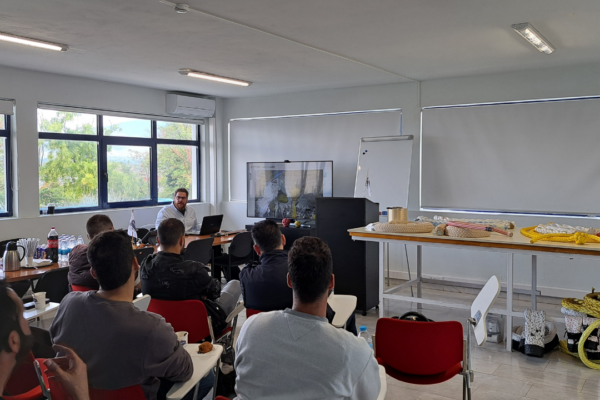
Use the Inspection guide by Katradis to verify your ropes condition or choose on-ship training by our experts. We ensure operation safety on tankers, bulk carriers, LNG and LPG vessels and any other large vessel.
As our client, we will ask you to provide us with general information about the proposed application and intended service of the line, such as:
HMPE ropes have a functional performance equivalent to steel. These lines have many benefits due to their high strength to weight properties, their equal performance with a lower diameter and their ease of handling. Their low elongation, high strength and extremely high tenacity make them the best choice for mooring lines.
Rope jackets provide extra protection from exposure to external mechanical damage, ingress of debris and UV degradation. However, jacketed ropes can’t undergo visual inspection easily, and are somewhat more difficult to splice.
See our article on how to splice double braided ropes.
By choosing Katradis HMPE ropes your ship meets MEG4 mooring requirements, and your staff is safe on deck. Replacement lines should be compatible with the mooring design, meaning that they have sufficient strength, appropriate stiffness and are compatible with the ship’s deck equipment.
If changing from steel wire ropes to HMPE ropes, a change process plan should be followed so that every member of the ship’s staff is properly informed.
The effective maintenance and inspection routine of any mooring line is critical to long term service and risk mitigation. Operators should create a policy for line maintenance, after consulting with their line manufacturer.
Mooring tails serve as an integral part of the mooring system, and should not be considered a weak link in the system’s design.
Maintenance routine intervals should be regular, and the entire length of line should be inspected by a competent person. Attention should be paid to those sections of line that are proven by experience to be the main areas of deterioration, such as spliced eyes and interface areas with winches, capstans, bollards, fairleads and rollers.
Maintenance activities for conventional fiber lines may include the following:
It is recommended that mooring lines are replaced when their residual strength reaches 75% of the ship design MBL. This reduction can be ascertained through a combination of destructive testing, historical record keeping, visual examination and other non-destructive condition monitoring techniques.
The following image shows the distribution of load when lines are used as stand alone mooring equipment and when they are combined with tails.
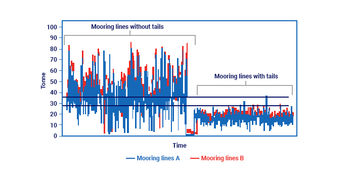
Specific projects may require longer tails due to certain conditions, such as longer wave periods. It is recommended that mooring analysis studies are carried out to verify the optimum combination of tail material and length in these instances.
To sum things up, following the MEG4 guidelines means that you should have understood and implemented the following:
These seven brief descriptions are the synopsis of operating procedures and risk assessments that ensure the safety and occupational health and wellbeing of the ship’s staff when using mooring equipment or operating in the mooring workspace.
The following measures are also recommended to mitigate the risk to personnel:
It is recommended that users and manufacturers continue to collaborate on new test methods. You can use whatever processes, documents and testing methods are necessary to ensure the most appropriate product is chosen for the intended use. We will continue to produce, test and document design lines or tails so that we offer you the best line properties possible.
The results of the tests are used to indicate the performance of the line or tail. As a conscious manufacturer, we develop documentation to ensure the material, construction and fabrication of the mooring line or tail can be reliable upon installation, maintenance, operation and retirement.
You can contact us anytime, if you are having difficulty comparing data, e.g. if the performance indicators or design parameters have been presented in a way that comparison is hard.
Effective ship mooring management requires knowledge of good mooring principles and
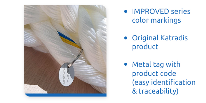
the ship’s overall mooring capability. All mooring lines, wires and tails should be received with certificates from the manufacturer. When you buy Katradis products, on receipt, every mooring line and tail is permanently marked so that positive identification of each line and the corresponding certificate and service history can be tracked.
Do you want to facilitate safe and effective mooring, unmooring and line tending operations with minimum demand and risk to personnel? Enable safe and effective mooring in a wide range of environmental conditions both at conventional and unconventional terminals with Katradis mooring ropes.
Choose your procurement from Katradis to:
Follow our social media pages on Facebook, Instagram and LinkedIn and keep in touch with us to learn more on our products and marine solutions.