Introducing Marine Expert Pro: Your AI-Powered Marine Advisor
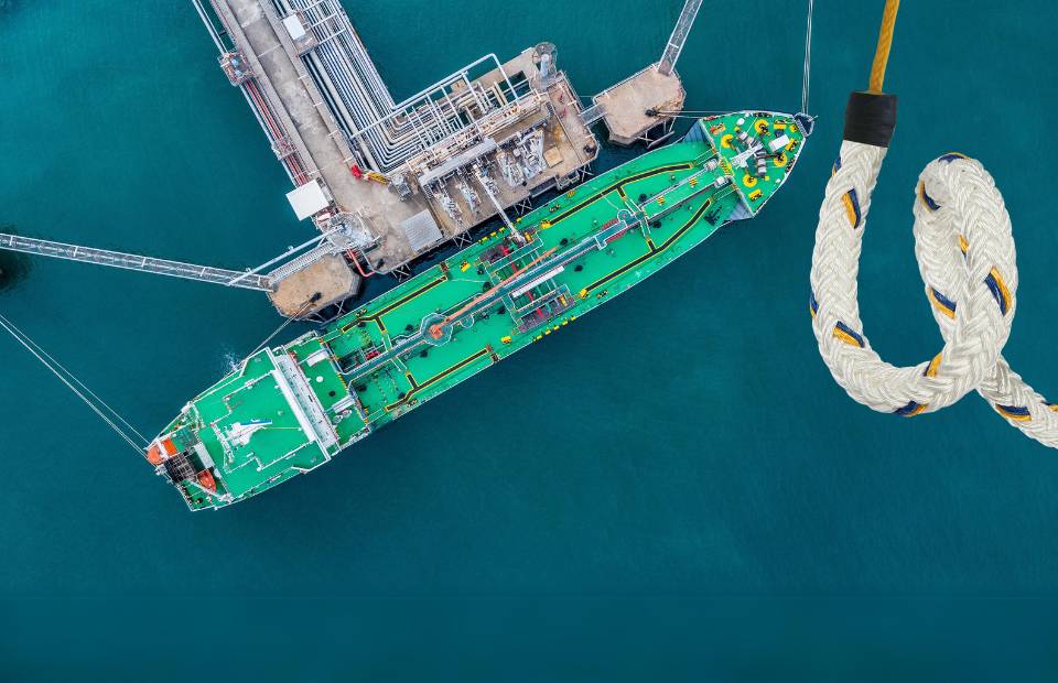
Marine Expert Pro has been developed by Katradis Marine Ropes Industry S.A. to provide an innovative, AI-powered solution tailored specifically for the maritime sector. This advanced tool leverages Artificial Intelligence...